
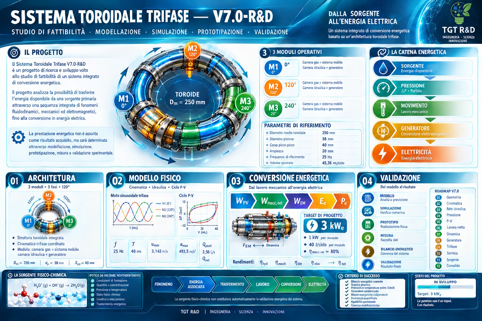
Three-Phase Toroidal System — V7.0-R&D
FEASIBILITY STUDY · MODELING · SIMULATION · PROTOTYPING · EXPERIMENTAL VALIDATION
The Three-Phase Toroidal System V7.0-R&D is a research and development project focused on the study of an integrated energy conversion system based on a three-phase toroidal architecture.
The architecture is designed to integrate physical, fluidic, mechanical, electromagnetic, and physicochemical phenomena within a unified conversion system, with the aim of characterizing its energetic and exergetic performance and experimentally determining its potential.
The project integrates geometric, kinematic, hydraulic, dynamic, electromagnetic, and thermophysical modeling, linking the energy source to mechanical motion and mechanical motion to electrical conversion.
MODEL → SIMULATION → PROTOTYPE → MEASUREMENT → ENERGY BALANCE → VALIDATION
The V7.0-R&D is designed to experimentally determine the actual potential of the architecture and the integrated energy source.
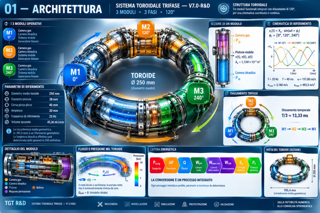
01 — ARCHITECTURE
3 MODULES · THREE-PHASE CONFIGURATION · 120° PHASE SHIFT
M1 — 0° · M2 — 120° · M3 — 240°
The system consists of three functional modules integrated into a toroidal structure, each associated with one phase of the three-phase configuration.
The 120° phase shift enables the coordinated behavior of the three modules, the distribution of forces, the work per cycle, and the overall energy conversion process to be investigated.
Each module comprises:
- gas chamber;
- moving assembly;
- hydraulic chamber;
- electromechanical conversion system;
- measurement and data acquisition system.
REFERENCE PARAMETERS
- Mean Toroidal Diameter: 250 mm
- Piston Diameter: 38 mm
- Peak-to-Peak Stroke: 40 mm
- Amplitude: 20 mm
- Reference Frequency: 25 Hz
- Volume spostato: ≈ 45,36 mL/ciclo
The mean geometric circumference, approximately 785.4 mm, serves as a geometric reference for the architecture.
The effective hydraulic length will be determined by the final CAD geometry and the configuration of the fluidic network.
FROM ENERGY SOURCE TO MECHANICAL MOTION
The model distinguishes between the pressure associated with the energy source and the pressure effectively available to the moving assembly:
Pₛₒᵣg → Pᴳ → ΔP → MOTION
where:
ΔP = Pᴳ − Pᴴ
where:
- Pᴳ = gas chamber pressure;
- Pᴴ = hydraulic chamber pressure;
- ΔP = differential pressure acting on the moving assembly.
The differential pressure provides the link between the energy source and the system dynamics.
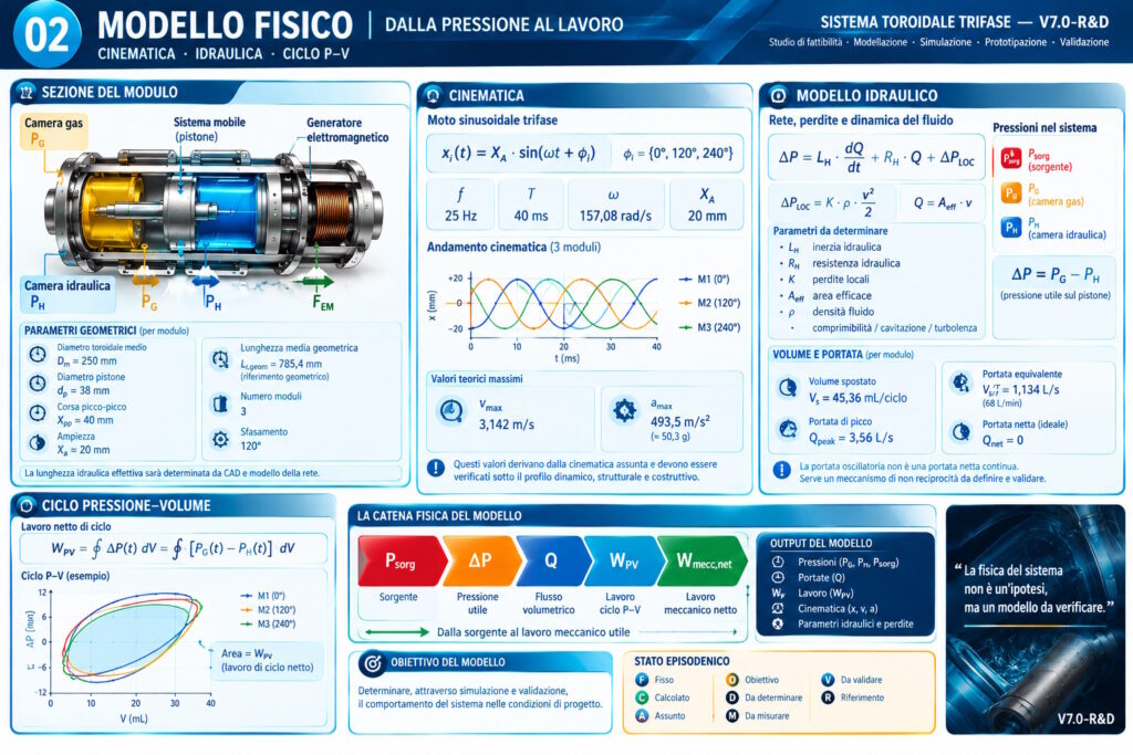
02 — PHYSICAL MODEL
KINEMATICS · HYDRAULICS · P–V CYCLE
The preliminary model considers a three-phase sinusoidal motion:
xᵢ(t) = Xₐ · sin(ωt + φᵢ)
where:
φᵢ = {0°, 120°, 240°}
and:
- f = 25 Hz
- T = 40 ms
- ω = 157,08 rad/s
- Xₐ = 20 mm
These parameters theoretically yield:
vₘₐₓ ≈ 3,142 m/s
aₘₐₓ ≈ 493,5 m/s² ≈ 50,3 g
These values define the reference kinematic behavior and provide the basis for subsequent dynamic, structural, and manufacturability assessments.
VOLUME AND FLOW RATE
For each module:
Vₛ ≈ 45,36 mL/ciclo
Vₛ / T ≈ 1,134 L/s ≈ 68 L/min
The theoretical peak flow rate associated with the sinusoidal motion is:
Qₚₑₐₖ ≈ 3,56 L/s ≈ 214 L/min
In the ideal sinusoidal reciprocating model:
Qₙₑₜ = 0
The oscillatory flow rate therefore represents the reciprocating motion of the fluid.
Any nonzero net flow depends on the fluidic configuration and the presence of a mechanism that breaks flow reciprocity.
HYDRAULIC MODEL
The preliminary behavior of the network is represented in terms of:
ΔP = Lᴴ · dQ/dt + Rᴴ · Q + ΔPᴸᴼᶜ
where:
ΔPᴸᴼᶜ = K · ρ · v² / 2
The model considers:
- fluid inertia;
- distributed losses;
- minor losses;
- compressibility;
- flow regime;
- turbulence;
- cavitation;
- Geometric characteristics of the network.
Scientific English Translation
The relevant parameters will be determined through modeling, simulation, and experimental characterization.
PRESSURE–VOLUME CYCLE
The work associated with the cycle is determined by:
Wᴾⱽ = ∮ ΔP(t) · dV
i.e.:
Wᴾⱽ = ∮ [Pᴳ(t) − Pᴴ(t)] · dV
The area enclosed by the cycle P–V constitutes the basis for determining the net work of the cycle.
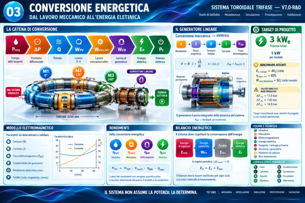
03 — ENERGY CONVERSION
FROM MECHANICAL WORK TO ELECTRICAL ENERGY
The energy conversion chain is investigated through:
Pₛorg → ΔP → Q → Wᴾⱽ → Wₘₑcc,net → Wᴱᴹ → Eₑ → Pₑ
The net mechanical work accounts for the work produced by the cycle and the losses associated with the fluidic, mechanical, and electromagnetic subsystems:
Wₘₑcc,net = Wᴾⱽ − Wₚₑᵣdᵢₜₑ
ELECTROMECHANICAL COUPLING
The linear generator is an integral part of the system dynamics.
The electromagnetic model accounts for:
V = R · I + dλ/dt
λ = λ(x,I)
Fᴱᴹ = Fᴱᴹ(x,I)
The electromagnetic force is fed back into the system dynamics:
mₑq · ẍ = Aₚ · ΔP − Fₗₒₛₛ − Fᴱᴹ
The generator therefore constitutes an integral part of the system dynamics. electromechanical load coupled to the motion, directly contributing to the system dynamics and energy conversion.
OVERALL EFFICIENCY
The conversion process is analyzed through:
ηₜₒₜ = ηₕyd · ηₘₑch · ηᴱᴹ · ηₑₗₑc
Overall efficiency depends on the actual characteristics of the individual subsystems and their interactions.
DESIGN TARGETS
Pₑ,total = 3 kWₑ
The value of 3 kWₑ constitutes the reference design target for the V7.0-R&D.
As a preliminary reference:
Pₑ,module = 1 kWₑ
Eₑ,module = 40 J/ciclo
ηₘₑcc→e = 80%
from which:
Wₘₑcc,benchmark ≈ 50 J/ciclo/modulo
These values serve as design references for the development of the architecture and for comparison among the model, simulation, and prototype.
TARGET ≠ RESULT
The actual achievable electrical power will be determined by the integrated behavior of the energy source, fluidic system, mechanical dynamics, and electromagnetic conversion.
The value of 3 kWₑ therefore represents a design objective rather than a demonstrated result.
ENERGY BALANCE
Energy performance is analyzed through an overall energy balance:
Eᵢₙ = Eₑ + Eₗₒₛₛ + ΔEₛₜₒᵣₑd
The energy balance accounts for:
- all external energy inputs required for operation;
- energy transferred through the conversion process;
- electrical energy delivered to the load;
- fluidic losses;
- mechanical losses;
- electromagnetic and electrical losses;
- temporarily stored energy.
Under steady-state periodic operation:
ΔEₛₜₒᵣₑd → 0
The energy balance enables the determination of the relationship among available energy, transferred energy, and overall losses.
PHYSICOCHEMICAL SOURCE
A central component of V7.0-R&D involves the study of the the energy and exergy potential associated with the source and the physicochemical transformations involved in the cycle.
The analysis distinguishes the energy content associated with a transformation from the fraction of energy that can be effectively transferred and converted through the architecture.
IONIC STATE
In the physicochemical model, the formation of ionic species associated with water is considered:
2 H₂O ⇌ H₃O⁺ + OH⁻
The species H₃O⁺ and OH⁻ therefore represent a specific physicochemical state under investigation.
The formation, persistence, distribution, and subsequent transformation of these species must be analyzed as a function of the operating conditions, physicochemical environment, interfaces, and energy-transfer mechanisms.
The scientific literature further shows that the behavior of ionic species varies significantly depending on whether they are present in liquid water, at an interface, or in the gas phase.
THERMOCHEMICAL REFERENCE
For the transformation considered in the model:
2 H₂O(g) → H₃O⁺(g) + OH⁻(g)
the thermochemical reference must be associated with specific thermodynamic states and reference conditions.
The corresponding value for the reverse transformation:
H₃O⁺(g) + OH⁻(g) → 2 H₂O(g)
represents the enthalpy change of the reaction.
This value must not be interpreted directly as available mechanical or electrical energy.
The amount of energy that can actually be transferred to the system must be determined by considering:
- the energy required to form the ionic state;
- operating conditions;
- the actual transformation pathway;
- heat transfer;
- mass transfer;
- interactions with surfaces and interfaces;
- thermal, mechanical, and electromagnetic losses;
- overall energy balance.
H₂/O₂ GAS PHASE
The source configuration also includes a H₂/O₂-based gas phase, considered part of the physicochemical pathway under investigation.
The reference transformation is:
2 H₂(g) + O₂(g) → 2 H₂O(g)
The H₂/O₂ recombination is considered in the model as a a distinct secondary process relative to the investigation of the H₃O⁺/OH⁻ ionic state.
Any initiation by means of a spark constitutes an activation mechanism for the transformation and must be included in the overall energy balance.
The energy associated with H₂/O₂ recombination must therefore be evaluated together with the energy required for the formation, separation, maintenance, and management of the species involved.
V7.0-R&D does not assume that the presence of H₂/O₂ inherently constitutes the primary source of available energy.
ENERGY · EXERGY · TRANSFER
The model distinguishes between:
ENERGY OF THE TRANSFORMATION → EXERGY ASSOCIATED WITH THE STATE AND OPERATING CONDITIONS → ENERGY TRANSFER → PRESSURE / MECHANICAL WORK → ELECTROMECHANICAL CONVERSION → ELECTRICAL ENERGY
The objective of V7.0-R&D is to determine what fraction of the energy and exergy potential actually associated with the source can be transferred and converted through the toroidal architecture.
Exergy must be determined relative to defined reference thermodynamic conditions and based on the experimentally characterized properties of the source.
PROJECT STATUS
DEVELOPMENT ACHIEVED
- MATHEMATICAL MODELING
- GEOMETRIC AND KINEMATIC ANALYSIS
- HYDRAULIC AND DYNAMIC MODELING
- PRELIMINARY ELECTROMAGNETIC MODELING
- PHYSICOCHEMICAL ANALYSIS
- Definition of the energy architecture
- Definition of the experimental verification methodology
- Establishment of the prototyping and validation pathway
These elements provide the technical foundation for advancing V7.0-R&D toward prototype development and characterization.
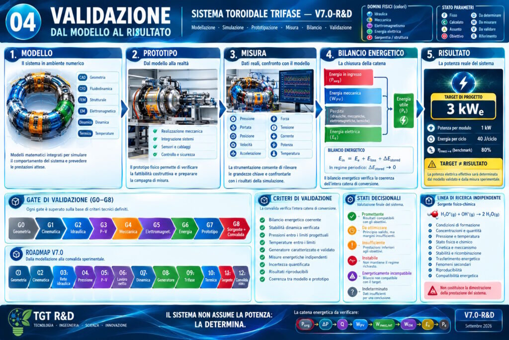
04 — VALIDATION AND DEVELOPMENT
FROM MODEL TO PROTOTYPE
V7.0-R&D follows an integrated progression:
CAD → CFD → DYNAMICS → FEM → ELECTROMAGNETICS → THERMAL ANALYSIS → PROTOTYPE → MEASUREMENT → VALIDATION
The experimental campaign will enable the correlation of the system’s key physical quantities with the model predictions.
MECHANICS AND FLUID DYNAMICS
PRESSURE · FLOW RATE · POSITION · VELOCITY · ACCELERATION · FORCE
ELECTRICAL AND THERMAL
VOLTAGE · CURRENT · POWER · TEMPERATURE
Comparison between the model and the prototype will enable determination of the actual behavior of the architecture and its corresponding energy balance.
ROADMAP V7.0
01 — GEOMETRY → 02 — KINEMATICS → 03 — HYDRAULIC NETWORK → 04 — PRESSURE → 05 — P–V → 06 — NET WORK → 07 — DYNAMICS → 08 — GENERATOR → 09 — THREE-PHASE → 10 — THERMAL → 11 — SOURCE → 12 — VALIDATION
DESIGN GATE
G0 — GEOMETRY
G1 — KINEMATICS
G2 — HYDRAULICS
G3 — P–V
G4 — MECHANICS
G5 — ELECTROMAGNETISM
G6 — ENERGY
G7 — PROTOTYPE
G8 — SOURCE + INTEGRATED VALIDATION
Each gate represents a development stage of the architecture and is associated with technical criteria, measurable data, and verifiable results.
PERFORMANCE CRITERION
The outcome of V7.0-R&D will be determined by the consistency among:
- source behavior;
- dynamic stability;
- fluid-dynamic performance;
- electromechanical conversion;
- energy balance;
- independent measurements;
- measurement uncertainty;
- experimental repeatability;
- consistency between the model and the prototype.
The achievable electrical power will therefore be determined by the experimentally measured performance of the system as a whole.
Pₑ IS NOT AN INPUT
Pₑ IS A QUANTITY TO BE DETERMINED
The electrical power actually obtainable will be determined through the following progression:
Pₛorg → ΔP → Q → Wᴾⱽ → Wₘₑcc,net → Wᴱᴹ → Eₑ → Pₑ
The result will emerge from the relationship between:
SOURCE → TRANSFORMATION → MOTION → CONVERSION → MEASUREMENT
Electrical power is therefore not assumed to be an automatic consequence of the model, but constitutes the final quantity to be determined experimentally.
V7.0-R&D
FROM NUMERICAL FEASIBILITY TO EXPERIMENTAL VALIDATION
TGT R&D · ENGINEERING · SCIENCE · INNOVATION
The potential of V7.0-R&D is not defined solely by the nominal value of the initial configuration, but by the architecture’s ability to transfer, control, and convert the energy associated with the source in a measurable manner.
V7.0-R&D is designed to assess this feasibility through modeling, simulation, prototyping, measurement, and energy balance.
Project V8.2 — Experimental Study and Development
Within the scope of the activities of research and were developed Several studies were conducted. and design configurations dedicated to potential systems for energy transition.
Among these is the Project V8.2, a theoretical study concerning a three-phase toroidal system with hydraulic recirculation and electromagnetic energy conversion.
The configuration shown below represents one of the configurations developed design configurations developed and incorporates into a single configuration in a concise form, the architecture, sizing, and modeling physical modeling and energy analysis and key parameters of the design.
The project is currently under investigation and does not constitute an experimentally validated technology. The reported quantities shown in the infographic are derived from from assumptions and models and theoretical calculations and have yet to be undergo experimental validation.
The subsequent phase of development will require the the assessment of feasibility, the development of a prototype, the execution of experimental tests, and the acquisition of instrumental measurements required to determine the actual performance of the system and to verify the balance overall energy balance.
The experimental results may confirm or modify or, where applicable, refute the formulated hypotheses put forward in the study.
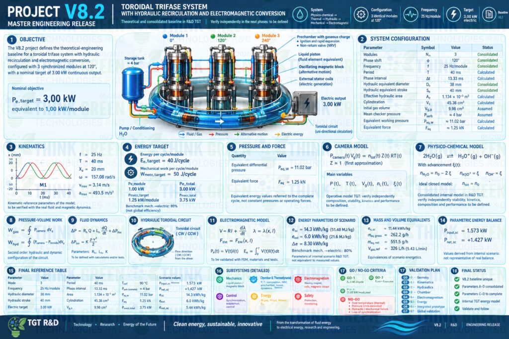
Caption:
V8.2 – Theoretical reference configuration and main design parameters.
The reported values represent theoretical results and preliminary design assumptions and do not constitute experimentally validated performance.
RELATED SCIENTIFIC SECTION
STATE OF THE ART — H₃O⁺ · OH⁻ · PROTON TRANSFER · NEUTRALIZATION
Scientific research has investigated H₃O⁺ and OH⁻ under a range of physical conditions, from solvation in liquid water and water–solid and water–vapor interfaces to the neutralization of isolated ions in the gas phase.
The references provided below are used exclusively to document the specific physicochemical phenomena.
They do not constitute validation of V7.0-R&D.
2011 — RECOMBINATION OF H₃O⁺ AND OH⁻ IN WATER
Hassanali, Prakash, Eshet, and Parrinello investigated the microscopic mechanism of H₃O⁺ and OH⁻ recombination in liquid water using ab initio molecular dynamics.
The study shows that neutralization is associated with a collective reorganization of the hydrogen-bond network and a concerted proton transfer. The process occurs on a picosecond timescale.
The study provides a reference framework for the microscopic mechanism of neutralization in liquid water.
It does not demonstrate macroscopic production of mechanical work or electrical energy.
On the recombination of hydronium and hydroxide ions in water – PubMed
2015 — WATER DYNAMICS AROUND H₃O⁺ AND OH⁻
Roy and Dang investigated the exchange dynamics of water molecules around H₃O⁺ and OH⁻ using molecular dynamics simulations.
The study highlights differences in the solvation dynamics of the two species and provides a reference for understanding the relationship between ions, water structure, and molecular mobility.
Water exchange dynamics around H3O+ and OH- ions | Journal Article | PNNL
2020 — ION FORMATION AND MIGRATION AT INTERFACES
Lentz and Garofalini investigated the formation and migration of H₃O⁺ and OH⁻ at interfaces using molecular dynamics simulations. water/silica interfaces and water/vapor interfaces under a static electric field.
The study shows that interfacial conditions and the electric field can influence the structure of water and the distribution of ionic species.
This reference is particularly relevant to the study of systems in which the following coexist:
WATER · GAS/VAPOR · SURFACES · ELECTRIC FIELDS · IONIC SPECIES
In this case as well, the result concerns the physicochemical behavior of the species and does not constitute evidence of macroscopic energy production.
Formation and migration of H3O+ and OH− ions at the water/silica and water/vapor interfaces under the influence of a static electric field: a molecular dynamics study | Physical Chemistry Chemical Physics | The Royal Society of Chemistry
2023 — FORMATION OF H₃O⁺ AND OH⁻ IN THE GAS PHASE
Catone, Castrovilli, Nicolanti, Satta, and Cartoni investigated the formation of H₃O⁺ and OH⁻ through reactions involving CO₂ e N₂O under conditions representative of the atmospheric environment.
The study is relevant because it documents processes leading to the formation of ionic species in the gas phase, distinguishing this behavior from the simple autoionization of liquid water.
The reference is relevant to the gas-phase component of the V7.0-R&D system, but it does not demonstrate the specific energy-conversion mechanism proposed by the project.
Formation of H3O+ and OH by CO2 and N2O trace gases in the atmospheric environment† | Physical Chemistry Chemical Physics | The Royal Society of Chemistry
2024 — NEUTRALIZATION OF ISOLATED H₃O⁺ AND OH⁻
Bogot and co-workers experimentally investigated the mutual neutralization of isolated H₃O⁺ and OH⁻ using the DESIREE facility.
The study identified multiple product channels and showed that gas-phase neutralization can involve electron transfer and proton transfer, rather than being represented simply as a single pathway:
H₃O⁺ + OH⁻ → 2 H₂O
This result is particularly important for V7.0-R&D because it demonstrates that the microscopic pathway of neutralization depends on the physical conditions of the system.
Consequently, the H₃O⁺/OH⁻ transformation must be experimentally characterized under the specific conditions of the project.
The mutual neutralization of hydronium and hydroxide – PubMed
RELATED SCIENTIFIC FRAMEWORK
The references cited above allow four distinct levels to be identified:
01 — FORMATION
H₂O ⇌ H₃O⁺ + OH⁻
The formation of ionic species depends on the physicochemical conditions of the system.
02 — SOLVATION AND PROTON TRANSFER
H₃O⁺ / OH⁻ → PROTON TRANSFER → TRANSPORT
The dynamics of the ionic species depend on the molecular environment and the structure of water.
03 — INTERFACES
SURFACE + WATER + GAS/VAPOR + ELECTRIC FIELD
Interfaces can alter the distribution and dynamics of ionic species.
04 — NEUTRALIZATION
H₃O⁺ + OH⁻ → NEUTRALIZATION PRODUCTS
The actual path depends on the physical conditions and the underlying microscopic mechanism.
SCIENTIFIC REFERENCES
- Hassanali, A.; Prakash, M. K.; Eshet, H.; Parrinello, M. (2011) — On the recombination of hydronium and hydroxide ions in water. Proceedings of the National Academy of Sciences, 108(51), 20410–20415. DOI: 10.1073/pnas.1112486108.Roy, S.; Dang, L. X. (2015) — Water exchange dynamics around H₃O⁺ and OH⁻ ions. Chemical Physics Letters, 628, 30–34. DOI: 10.1016/j.cplett.2015.04.002.
On the recombination of hydronium and hydroxide ions in water – PubMed - Lentz, J.; Garofalini, S. H. (2020) — Formation and migration of H₃O⁺ and OH⁻ ions at the water/silica and water/vapor interfaces under the influence of a static electric field: a molecular dynamics study. Physical Chemistry Chemical Physics, 22, 22537–22548. DOI: 10.1039/D0CP03656K.
Water exchange dynamics around H3O+ and OH- ions | Journal Article | PNNL - Catone, D.; Castrovilli, M. C.; Nicolanti, F.; Satta, M.; Cartoni, A. (2023) — Formation of H₃O⁺ and OH by CO₂ and N₂O trace gases in the atmospheric environment. Physical Chemistry Chemical Physics, 25, 25619–25628. DOI: 10.1039/D3CP02427J.
Formation and migration of H3O+ and OH− ions at the water/silica and water/vapor interfaces under the influence of a static electric field: a molecular dynamics study | Physical Chemistry Chemical Physics | The Royal Society of Chemistry - Bogot, A.; Poline, M.; Ji, M. C.; Dochain, A.; Simonsson, A.; Rosén, S.; Zettergren, H.; Schmidt, H. T.; Thomas, R. D.; Strasser, D. (2024) — The mutual neutralization of hydronium and hydroxide. Science, 383(6680), 285–289. DOI: 10.1126/science.adk1950.
Formation of H3O+ and OH by CO2 and N2O trace gases in the atmospheric environment† | Physical Chemistry Chemical Physics | The Royal Society of Chemistry
Bogot, A.; Poline, M.; Ji, M. C.; Dochain, A.; Simonsson, A.; Rosén, S.; Zettergren, H.; Schmidt, H. T.; Thomas, R. D.; Strasser, D. (2024) — The mutual neutralization of hydronium and hydroxide. Science, 383(6680), 285–289. DOI: 10.1126/science.adk1950.
The mutual neutralization of hydronium and hydroxide – PubMed

